| |
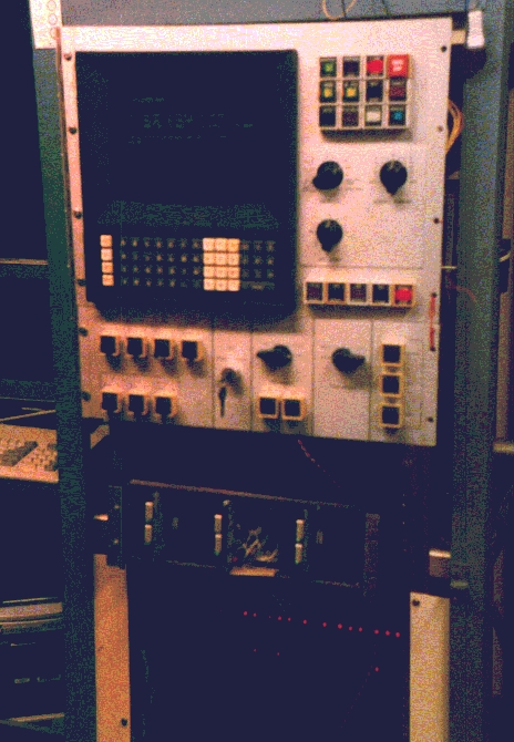
The Allen-Bradley 7320 CNC controller. Control panel, keyboard and CRT on top, my own servo amps in rack below, CPU of control below that. |
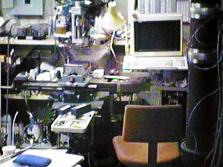 |
Here's a general view of the front of the mill. White unit in front is the Y-axis drive. it sticks out almost 18" from the knee. Fortunately, it is narrow, so it doesn't impede access to the table as much as you would think. The X axis mounting bracket and drive are at the right end of the table, a bit dark (sorry). |
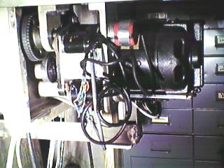 |
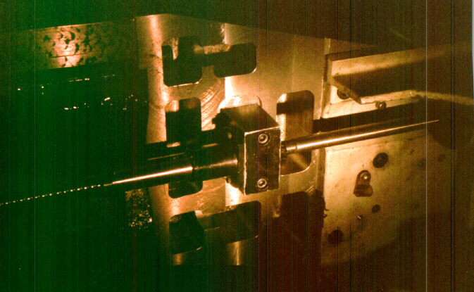
This is a view of the works inside each axis drive unit. The large object in back is the DC servo motor, 1/8 Hp. It drives the leadscrew with a toothed belt, held taut by a tension roller mounted on an eccentric. The small red unit at upper right is the Sumtak 1000 line encoder. By counting every transition you get 4000 counts/rev, and with a .2" lead screw, that gives .00005" per count. The small black item driven by the miniature toothed belt is the tachometer. The mini toothed belt goes from the encoder shaft (direct driven by the lead screw) to the tach and a 150:1 gearbox that originally drove a corrector cam that moved the resolver housing to correct for leadscrew errors. I left the rest of the mechanism out when changing over to the encoder, but I could put it back in with a little work. Right now, the gearbox serves as an idler only. At the upper right, you can see part of the sprocket by which the motor's toothed belt drives the leadscrew. |
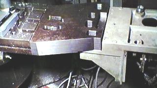 |
Here is the bracket that mounts the X axis drive to the table. it was carved out of a 111 Lb piece of 2.5" x 10" x 12" HRS. it has pockets milled out from both sides to lighten it. It now weighs about 48 Lbs, but still gives massive rigidity to the X screw and drive mounted to it. |
 |
This is a view of the X axis bracket from the underside. At the left, the thread of the leadscrew can be seen, as well as some of the hand frosting on the X-axis ways of the underside of the table. Some of the lightening pockets can be seen around the bearing block, near the center. This block has two angular contact bearings preloaded to constrain the leadscrew from moving axially. On the right, you can see part of the axis drive casting. |
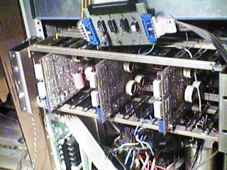 |
This is a closer picture of the servo amplifier rack. it has space for 5 axes, but right now I only have 3 installed. Behind the rack (no picture yet) is power switching for the servo amps, and a relay panel for the auxilliary control - coolant, spindle, E-Stop gating, etc. |
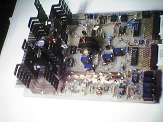 |
This is a closeup of the servo amp PC board. This one was drilled on this CNC system, with the CNC providing X and Y, and manual drill feed. Now, this amp drives the Z axis on the quill. This amp uses PWM (pulse width modulation) on a full bridge MOSFET switch, to drive DC motors up to 6 Amps and 80 Volts. With minor changes to a few part values, these amps should be able to go up to 180 Volts, and possible a little higher current. By moving the power transistors to external heatsinks and heavier wiring, there should be no limit on current. The circuit has two nested control loops, the inner one for motor current and the outer one for velocity. it has instrumentation amps for both velocity command and the tach feedback. it displays motor current and command voltage on LED bar graphs, with polarity arrow LEDs below. This amp also features extensive output filtering, so the 100 KHz PWM square waves are not applied to the motor, or allowed to radiate from the wires. |
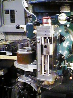 |
Here is a view of the front of the Bridgeport J head,
with the Z axis drive mounted to the front.
The little red Sumtak encoder can be seen at the top,
direct driven from the .1" pitch leadscrew. The block
it is mounted to is made in two pieces, with some
internal areas opened up to make room for sprockets and
mini cog belts for the tach. No idler is used here,
the tach is on a slotted bracket for tensioning.
The two small holes in the front provide access to the
setscrews for the sprocket and the shaft encoder's
flexible coupling. For more info on this Z axis
drive from scratch, see The piece riding the leadscrew below the encoder is a one-piece replacement for the stop ring that bolts to the quill through the slot in the front of the main head casting. it has a complex shape with two angled sides and a 180 degree round front. This was done with the 2-axis CNC, before the Z was completed. The round flange of the ball nut bolts to the bottom of this adapter. The screws lined up perfectly, which seemed like a miracle to me. The Z axis drive motor is at the left, nestled into a hollow in the main casting. Its bracket was also made with 2 angled sides and a rounded part. I bolted it to a 'sacrificial' and milled the whole outline in one coordinated motion, using cutter diameter compensation. I first set the compensation larger than the actual tool diameter for a roughing pass, and then reduced the diameter I told the CNC about to make closer and closer passes, until I actually entered the true tool diameter for the finish pass. A drive sprocket can barely be discerned under the bottom bearing block, which has two preloaded angular contact bearings. The motor is from a Hitachi mainframe-class tape drive, and is a Yaskawa ironless-rotor minertia servo motor. I'd hate to even know what that motor cost. It's rated at 28 V, 14.5 A! |
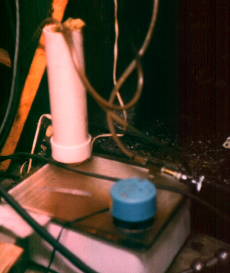 |
This is my flood coolant system. It is an enamel vegetable cooler from an 1950's Frigidaire. it holds about 2 gallons to properly submerge the Little Giant pump. The white PVC pipe in the back is a return filter. Coolant can be circulated from the pump through the filter for aeration purposes. The return fluid runs through a handi-wipe for collection of big chips, then runs through a stack of window air conditioner foam refill material and then several handi wipes, all cut into discs to fit the 1 1/4" to 3" reducing fitting. That all sits on a piece of Plexiglas with many 1/4" holes drilled in it. The bottom of the PVC tube is grooved and O-ringed, so the fluid can back up a bit in the pipe. If you fill the tank with the right amount of coolant, then the pump will starve out before the filter overflows. There is a Plexiglas cover fitted to the top of the tank, to keep out chips and slow evaporation. No, I don't know how to keep synthetic coolants from going rancid - a big problem! |