Jon Elson's Machining Page
Upgrading CNC on a PC platform
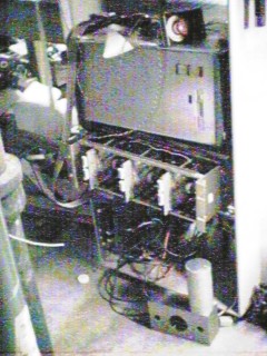 |
Equipment rack with customized rack-mount cabinet for
the PC motherboard, power supply, drives, etc. the
rack of servo amps, and the big DC power supply for
the servos. |
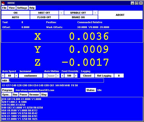 |
A view of the EMC screen showing the position readout in the center,
mode info and buttons on top, and a peephole view
of the toolpath program at the bottom. Just below the
position readout are jog speed and jog mode selection,
a list of the modal G and M codes currently in force,
and info on the toolpath program and buttons to control
it. The MDI line is where you type manual commands.
EMC can be run by the mouse, but almost every operation
can also be done just from the keyboard (that's how I
use it).
|
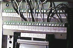 |
This is a terminal board I made for breaking out connections
from the 50-pin cables attached to the Servo-to-Go board. Here
the signals from the 3 shaft encoders come into the STG board,
on P3 (or P4 for axes 4-8) and the analog velocity commands go to the servo amps.
The 50-pin connector is a standard solder-mount male connector for
ribbon cable female connectors. The wire terminal blocks are
Phoenix Contact MKDSN 1,5/5-5.08 5-contact blocks, Digi-Key part # 277-1250.
The circuit board is single sided.
|
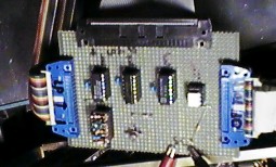 |
This is a hand-wired prototype of the emergency stop logic and
interface to the auxilliary outputs. It connects to the Servo-
to-Go card at P1, to the Opto-22 compatible solid-state relays,
and to the parallel port for aux. signals. It also brings out
the ends of the 'safety chain' of fault switches and E-stop
buttons. A green light indicates the safety chain is in the 'OK'
condition. It senses the safety chain, the Servo-to-Go's watchdog
timer and the digital output bit used to command e-stop from
EMC, and trips the E-stop flip-flop due to any of these conditions.
It also notifies EMC through a digital input bit if E-stop has been
tripped. Finally, when E-stop is tripped, it cuts off +5 V
to the opto-22 board, to shut down any auxilliary devices (like
the spindle!) when an E-stop occurs, even if the CPU is not functioning
properly to do that.
|
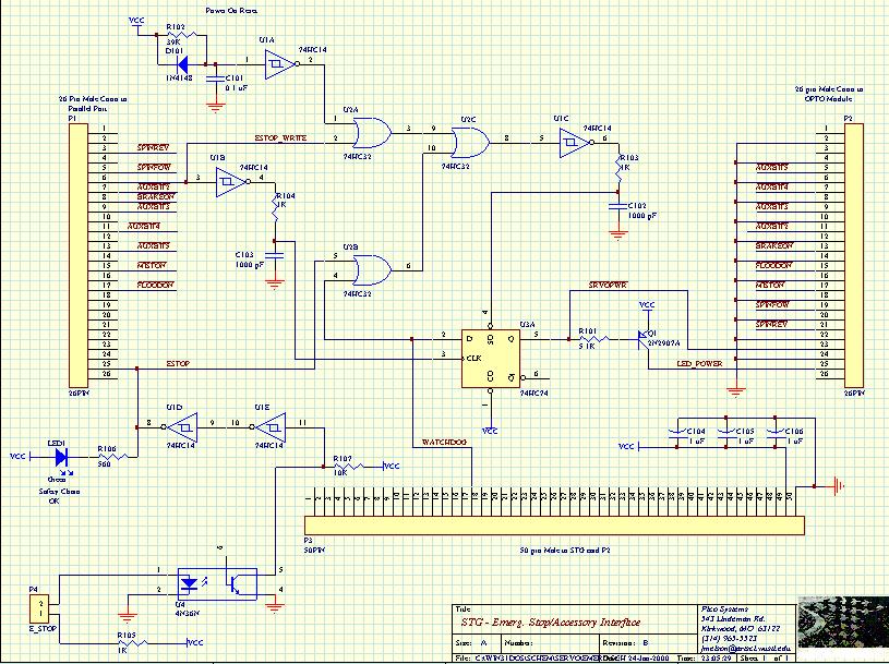 |
This is a schematic for the above board. I can e-mail a better
copy in PostScript or HPGL.
|
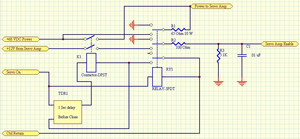
This is the circuit that ramps the DC power to the servo amps
up and down, when coming out of, or going into E-Stop, respectively.
The 24 V AC input is controlled by the first Grayhill SSR
module, so when EMC and the safety board above both agree
that all is OK, then this chain of relays is engaged.
The first relay, RY1 is a small, general purpose relay, and
engages immediately. This connects R1 between the DC supply
and the servo amps, and the capacitors in the servo amps
begin charging. One second later, the delayed-on relay,
TDR1 closes its contacts, and the power contactor K1
closes. It provides a direct contact between the DC power
supply and the servo amps. Because the capacitors in the
servo amp are already charged, there is no large current surge.
Finally, an RC delay circuit (R2, R3 and C1) charges up,
enabling the servo amps a moment later.
The reverse sequence has all relays dropping out at (roughly)
the same time. This connects R1 so that it drains energy
from the servo amps, and permits braking of any motors in motion
through the protection diodes in the power FETs in the servo amps.
At the same time, the RC delay quickly drains energy from C1,
disabling the servo amps.
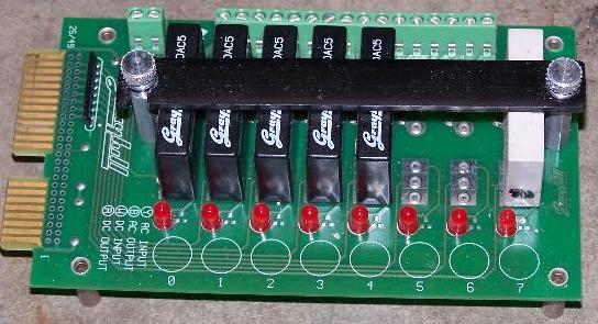 |
This is the grayhill I/O board which allows up to 8 solid
state relays or digital input modules to be mounted. The
connections to the emergency stop/logic interface board are
by means of a 26-conductor ribbon cable and card-edge connector.
The connactions to the power devices are by means of screw
terminals.
I have SSRs that enable the servo amplifiers, and start the
spindle forward, spindle reverse, mist and flood coolant,
and whatever else I add later, such as an automatic lube system.
|
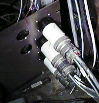 |
These are the plugs I use to connect the servo drive systems
to the CPU cabinet. They are 37-pin round plastic AMP connectors
from Digi-Key. There are plenty of pins for encoders, tach,
motor and limit switches.
|
To Home


