Pico Systems has developed a low-cost servo amplifier to drive brush motors of a motion-control system. It uses PWM (Pulse Width Modulation), a technique to reduce power dissipation in the amplifier to a minimum.
This amplifier takes in opto-isolated PWM and direction signals from a motion controller, and produces a filtered PWM drive waveform to the motor. It can operate from up to a 160 V DC power source, and can deliver up to 20 A to the load. It has user-settable cycle by cycle current limiting, and a separate, high-side overcurrent detector. If the overcurrent limit is tripped, the amp goes into fault status, a red LED lights, and a Solid State Relay indicates the problem to the controller.
The PWM frequency is determined by the motion controller, but should be between 25 and 100 Khz. The duty cycle can be reduced to zero, but must not reach 100%. Off time of at least 500 nS must be provided every cycle to recharge the "bootstrap" capacitors in the high-side transistor's gate drivers.
The polarity of the PWM pulse is set by default such that no current in the input to the optoisolator equals no current at the output of the amplifier. Normally, the input terminals to the optoisolator can be rewired to provide the opposite signal polarity. In cases where the motion controller lacks source or sinking capability, an optional jumper can be used to reverse this polarity on the amplifier.
The direction polarity is set so that no current in the direction optocoupler's input equals positive output at the MOT + terminal. There is no provision to switch this polarity, as reversing the two motor wires will serve this purpose.
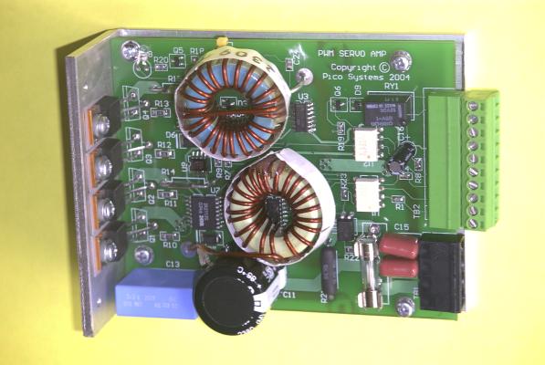
The amplifier is built on a 3.3 x 4" circuit board, with a metal bracket supporting the board and power transistors. The part of the plate where the transistors are mounted is intended to be bolted to a heat sink, but in low-current applications, the metal plate may provide sufficient heat removal. The entire volume taken by the amplifier is 1.5 x 3.3 x 4.25"
IMPORTANT NOTE: Especially when using over 100 V DC for the motor power supply, you MUST assure that the 12 V logic power is steady before the motor supply is turned on. You can use our power switch and braking module to do this, or use a relay on the motor supply input that is turned on when the PWM controller comes out of E-stop. If the motor supply comes up WHILE the 12 V supply is rising, it can cause all the power transistors to blow.
After the enable signal is brought to the +12 V level, activating the amplifier, it is necessary to send at least one on-time pulse with the direction input in each state to enable the FET drivers. These can be very short pulses on consecutive PWM cycles.
Connector Pinouts for the PWM Servo Amplifier
Mechanical drawing of the PWM Servo Amplifier
pre-machined heat sinks for the PWM servo amplifier
For more information, contact :
Jon Elson
Pico Systems
543 Lindeman Rd.
Kirkwood,  MO  63122
(314) 965-5523
or, email at : elson@pico-systems.com