Gecko 320/340 Interface Connector Pinout
Connectors :
| J1 is the connector to the Gecko axis 1. |
| J2 is the connector to the Gecko axis 2. |
| J3 is the connector to the Gecko axis 3. |
| J4 is the connector to the Gecko axis 4. |
| Pin # | Signal |
| 1 | Gecko Enc - |
| 2 | Err/Res |
| 3 | Phase B |
| 4 | Phase A |
| 5 | Enc + |
Note: If using the Gecko G320X, you need to add two 1K Ohm resistors between ENC +5 and A, and ENC +5 and B, to pull the quadrature signals up to logic levels acceptable to the G320X. These can be added either at the Gecko Interface end or on the G320X itself. The G320 had enough pull-up built into it, the G320X seems to need additional pull-up.
J5 provides the encoder signals to the computer.
For each axis, the encoder signals are A and B.
Pins are as follows :
| Pin # | Signal |
| 1 | + 5 V supply |
| 2 | Gnd |
| 3 | Axis 1 Phase A |
| 4 | Axis 1 Phase B |
| 5 | Axis 2 Phase A |
| 6 | Axis 2 Phase B |
| 7 | Axis 3 Phase A |
| 8 | Axis 3 Phase B |
| 9 | Axis 4 Phase A |
| 10 | Axis 4 Phase B |
| 11 | ground to enable |
| 12 | not used |
| J6 sends the fault condition to the computer.
It is an opto-coupler output, and can be used to
either pull to +5 V or ground as needed. It passes current when
no Gecko is in the fault condition.
Pins are as follows :
| J7 handles power to the Gecko drives.
When enabled by pin 11 of J5, power flows from
the DC supply to the Gecko drives. Any power
returned from the motors to the Gecko drives is allowed
to flow to the capacitors in the power supply.
When disabled, the power supply is disconnected, and
a braking resistor on the Gecko interface drains away
any power flowing from the motors, and safely brakes
them to a stop.
Pins are as follows :
| Pin # | Signal |
| 1 | DC Power Supply |
| 2 | Power to gecko drives |
| 3 | Power Supply Ground |
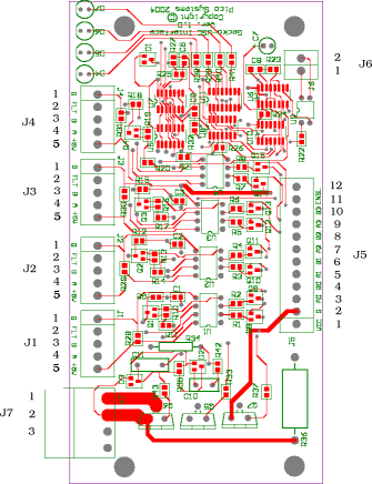 Board Layout Board Layout |
|
To Home
|